

Steel Mesh Welding Production Line Factory: Key Features for High-Quality Output
2026-08-26
In steel mesh welding, the gap between average and outstanding output often comes down to the production line itself. A factory that consistently delivers high-quality welded mesh doesn't achieve that by chance—it's engineered into every stage, from wire straightening to final mesh cutting. As construction and infrastructure projects place ever-greater demands on material strength and dimensional accuracy, knowing which factory features truly drive quality has become a practical necessity. YI ZHOU TECHNOLOGY has honed these features over years of innovation, turning intricate welding operations into smooth, repeatable processes. This post examines the key characteristics of a high-performing steel mesh welding production line factory—and what they mean for your project's success.
Precision Welding Controls That Keep Mesh Dimensions Consistent
Maintaining exact mesh dimensions during welding depends on controlling heat input and electrode placement with minimal variation. Using servo-driven weld heads, the downward force and contact time can be adjusted in fine increments, preventing excessive indentation or material displacement that would otherwise distort the grid pattern. Current pulses are regulated through inverter-based power supplies, ensuring each weld spot receives the same energy regardless of line voltage fluctuations or electrode wear.
A closed-loop inspection system monitors the finished weld zone immediately after each cycle. Laser micrometers or high-resolution cameras measure the distance between adjacent wires and compare it to a stored reference. If drift beyond a set tolerance is detected, the control unit automatically trims the welding current or adjusts the wire feed tension to bring the spacing back into range. This real-time correction eliminates the slow feedback loops typical of manual sampling, allowing a long production run to hold dimensional accuracy from the first panel to the last.
Fixture design plays an equally important role in keeping mesh dimensions stable. Precision-ground clamping plates and adjustable side guides hold the intersecting wires in a fixed grid before the electrode descends. Any accumulated thermal expansion is countered by spring-loaded supports that maintain consistent pressure without over-constraining the assembly. Regular checks on tooling alignment and electrode tip geometry further ensure that the weld nugget forms centered on the wire crossing, keeping the overall mesh width and pitch within a fraction of a millimeter.
Automated Wire Straightening and Feeding for Uniform Grid Openings
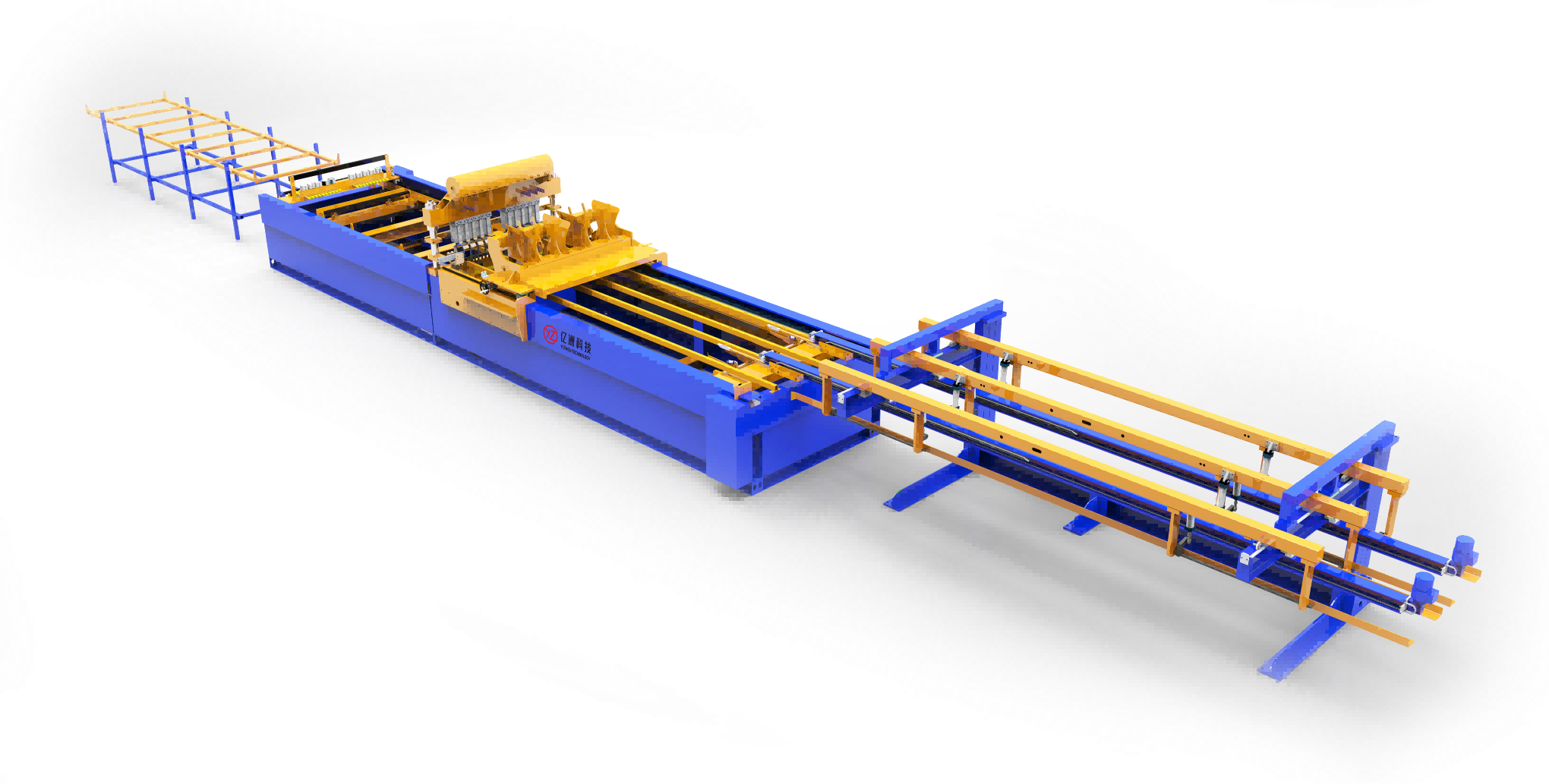
The straightening module uses a series of staggered rollers arranged in a slight offset pattern. As the wire passes through, each roller applies a controlled bending force in alternating directions, gradually removing any residual coil memory. The roller gap is set just below the wire diameter, forcing the material to flex past its yield point without work hardening the surface. This approach handles diameters from 2 mm to 8 mm without changing tooling, relying instead on adjustable spring-loaded roller banks that compensate for minor variations in incoming stock.
Feeding into the grid assembly station relies on a closed-loop servo drive paired with an optical encoder mounted near the cutting head. The encoder measures actual wire travel in real time, and the drive corrects for slip or stretch every few milliseconds. This keeps cut lengths within ±0.15 mm across a full production shift. The feed path is fully enclosed with polyurethane guide channels, preventing dust or scale from the straightening process from reaching the grid welding fixtures.
Grid opening uniformity comes from a two-stage clamp-and-release sequence. First, the straightening rollers hold the wire under slight tension while the servo advances the exact pitch distance. Then a fixed jaw clamps the wire while a movable jaw retracts, allowing the cut piece to drop into a preset nest without springback. The controller stores pitch offsets for different wire tensile strengths, so switching from mild steel to stainless requires no physical adjustments beyond selecting a recipe on the touch panel.
Heavy-Gauge Electrode Holders Built for Continuous Production Runs
These electrode holders are machined from thick, high-conductivity copper alloy plates that shrug off heat buildup during long weld sequences. The extra mass isn't just for show—it pulls thermal energy away from the tip and spreads it across the entire body, so tip temperature stays stable hour after hour. Operators notice the difference when the holder stays cool enough to touch near the joint, even after hundreds of cycles.
What sets these heavy-gauge units apart is how they handle mechanical stress. The thicker walls resist deflection under clamping force, which keeps electrode alignment true and prevents spatter from sneaking into the contact zone. In continuous production, that means fewer interruptions to re-dress tips or chase down intermittent weld quality issues caused by holder flex.
Field reports from stamping and tier-one assembly lines consistently mention one thing: these holders just keep running. No mysterious drops in nugget size mid-shift, no sudden need to crank up current to compensate for wear. The weight may feel substantial when swapping electrodes, but the trade-off is a process that stays predictable from first weld to last.
Programmable Logic Systems That Adjust Welding Patterns Without Downtime
Modern welding lines often face a stubborn trade-off: change the pattern for a new part, and you usually stop the cell, reprogram the controller, and lose valuable cycle time. Programmable logic systems sidestep this by storing multiple welding schedules directly in the controller's memory. Operators can switch from a lap joint on mild steel to a butt joint on stainless simply by selecting a preloaded recipe from the HMI. The logic controller reads the new parameters, adjusts wire feed speed, voltage, and travel motion instantly, and the torch keeps moving without a single missed beat.
What makes this possible is the tight integration between the motion planner and the weld sequencer. Instead of treating path generation and weld parameter control as separate islands, a unified logic core recalculates the torch trajectory and syncs it with pulse timing in real time. When a sensor detects a slight gap variation, the system can tweak the weave width or pause duration on the fly, all within the same scan cycle. This dynamic adjustment capability means the production line no longer needs to stop for minor part deviations or batch changeovers, which is a common source of hidden downtime in high-mix welding environments.
Field experience shows that plants using these adaptive logic systems often cut changeover time from twenty minutes to under one minute. The key is not just faster parameter switching, but the ability to validate the new pattern while the previous weld is still cooling. A background routine checks the logic conditions, verifies sensor feedback loops, and preloads the next recipe into the buffer. Once the operator gives the go-ahead, the transition is virtually seamless. This keeps weld quality consistent across different products and lets a single robotic cell handle a wider variety of jobs without constant manual reprogramming.
Inline Quality Checks That Catch Weak Joints Before They Leave the Line
A weak joint rarely announces itself until it's already failed in the field. That's why inline inspection stations have shifted away from spot-check sampling toward continuous, non-destructive evaluation at every cycle. For crimped wire terminals, a force-displacement signature from the press can flag insufficient barrel compression or strand slippage within milliseconds, while ultrasonic testing applied to welded busbar tabs compares the echo pattern against a stored reference for the exact material stack-up. The key is not just detecting a bad joint, but catching the drift before it becomes a reject—things like electrode wear on a resistance welder or a slightly worn crimp die show up as subtle shifts in the measured curve well before the joint actually falls below spec.
Thermal imaging offers another angle for joints that carry current or undergo friction welding. A weak connection has higher electrical resistance, so when a short pulse is applied during the production cycle, a poorly fused area shows up as a localized hot spot on the infrared camera. This works particularly well for battery tab-to-cell connections where a cold solder joint or incomplete laser weld might otherwise pass a simple visual check. Some lines combine this with active thermography—heating one side and watching the heat spread—to reveal voids or cracks hidden under a surface that looks perfectly smooth. The decision threshold is tuned for each joint design using a small batch of intentionally degraded samples, so the system learns to ignore normal variation in material thickness or ambient temperature.
What makes these inline checks truly effective is the immediate feedback loop they enable. When the system flags a weak joint, it doesn't just pull the part aside; it timestamps the event, stores the raw waveform or thermal image, and automatically notifies the upstream station operator. On a smart line, that data feeds a statistical process control chart that watches for trends—like a gradual increase in average crimp force or a widening spread in ultrasonic attenuation—so maintenance can swap out a tool before it starts producing bad parts. Over time, the inspection database becomes a valuable record for warranty analysis and helps engineers understand exactly which process variables correlate with field failures, without ever letting a suspect joint out the door.
Modular Station Design for Fast Reconfiguration of Mesh Panel Sizes
Instead of rebuilding the workstation every time a new mesh panel specification arrives, operators rely on a base frame fitted with standardized mounting points. Each panel size has a corresponding set of locating pins and clamp modules that slide into these points, letting the team swap from one configuration to the next in under fifteen minutes.
The heart of the system is a rail-and-cart arrangement. Rails run along two axes, and each cart carries a pre-set jaw assembly sized for a specific mesh panel width and length. When a different panel size is scheduled, the operator disengages two spring-loaded locks, rolls the old cart out, and rolls the new one in. No need to recalibrate the tension rollers or adjust the mesh feed path by hand.
This approach cuts down changeover time from nearly an hour to a fraction of that, even for small-batch runs. It also keeps the mesh alignment consistent across sizes because every cart is built to the same mounting datum. As a result, the same station can handle panels for window screens, security grilles, and filtration media without dedicated tooling for each product line.
FAQ
A top-tier line integrates precision servo-driven welding heads, real-time mesh alignment sensors, and adaptive current control so the weld penetration stays consistent even when wire diameter or spacing shifts slightly during a run.
Instead of relying on post-weld inspection alone, the line uses laser-measured cross wire placement and automatic pitch correction before every weld cycle, which keeps aperture tolerance within ±0.5 mm on high-volume batches.
Medium-frequency DC inverter welding is preferred because it delivers shorter, more controlled heat input. Combined with copper alloy electrode caps and active cooling, it produces strong joints while preserving the zinc layer near the weld zone.
Yes, modern systems use servo-driven mesh pulling and quick-change electrode cassettes. Operators can switch from a 50×50 mm aperture with 3 mm wire to a 100×100 mm aperture with 5 mm wire in under 20 minutes, and recipe-based controls store all parameters.
The line monitors weld current, electrode force, and nugget formation in real time. If a weld falls outside the set tolerance, the controller marks the sheet and automatically adjusts subsequent welds, so fewer than 0.3% of sheets require manual rework.
High-speed lines use twin-row welding carriages that fire alternately while the mesh advances continuously. This spreads mechanical wear and thermal load across two electrode sets, allowing 120–150 cycles per minute without sacrificing joint tensile strength.
Look for automatic electrode dressing stations, centralized lubrication, and open-architecture PLC diagnostics. These features let operators replace worn electrode caps during scheduled pauses and trace faults to a specific servo or sensor within minutes.
Incoming coils pass through multi-plane straightening rollers and a closed-loop length encoder. The encoder triggers the shear only when the wire is fully tensioned and straight, which eliminates end burrs and prevents cross-wire misfeeds at high acceleration.
Conclusion
A steel mesh welding production line built for high-quality output depends on precision controls at every stage. Welding controls hold mesh dimensions within tight tolerances, so panels do not drift out of square over long runs. Automated wire straightening and feeding keeps grid openings uniform, eliminating the skew and spacing errors that often appear with manual handling. Heavy-gauge electrode holders are designed for continuous production, resisting heat deformation and maintaining pressure consistency even under heavy daily cycles. Each station feeds into the next with minimal manual intervention, which reduces handling damage and keeps the line moving. These elements prevent the small inconsistencies that weaken finished mesh and slow down downstream assembly.
Programmable logic systems allow switching welding patterns without line stoppage, so changing panel sizes does not require hours of downtime. Inline quality checks run continuously, catching weak joints before panels leave the line and flagging defects that visual inspection might miss. Modular station design adds another layer of flexibility, letting the factory reconfigure for different mesh dimensions quickly. Together, these features keep output speed, dimensional accuracy, and joint strength balanced throughout the shift.
Contact Us
Contact Person: Sophia Jiang
Email: [email protected]
Tel/WhatsApp: +86 17367381818
Website: https://yzwelding.com/